
Quiz Summary
0 of 12 questions completed
Questions:
- 1
- 2
- 3
- 4
- 5
- 6
- 7
- 8
- 9
- 10
- 11
- 12
Information
You have already completed the quiz before. Hence you can not start it again.
Quiz is loading…
You must sign in or sign up to start the quiz.
You must first complete the following:
Results
Results
0 of 12 questions answered correctly
Time has elapsed
You have reached 0 of 0 point(s), (0)
Earned Point(s): 0 of 0, (0)
0 Essay(s) Pending (Possible Point(s): 0)
| Average score |
|
| Your score |
|
Categories
- Not categorized 0%
| Pos. | Name | Entered on | Points | Result |
|---|---|---|---|---|
| Table is loading | ||||
| No data available | ||||
- 1
- 2
- 3
- 4
- 5
- 6
- 7
- 8
- 9
- 10
- 11
- 12
- Answered
- Review
-
Question 1 of 12
1. Question
1 point(s)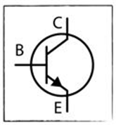
The transistor in the diagram is a _______ transistor.
CorrectIncorrect -
Question 2 of 12
2. Question
1 point(s)The potential of terminal C should be ________ when it is connected to a circuit.
CorrectIncorrect -
Question 3 of 12
3. Question
1 point(s)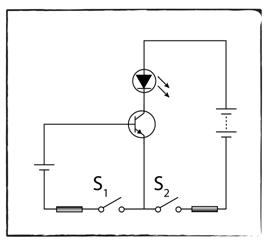
Which of the following is not true regarding the transistor circuit in the diagram?
CorrectIncorrect -
Question 4 of 12
4. Question
1 point(s)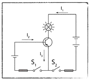
The diagram shows a transistor circuit. Which of the following is true about the current I1, I2 and I3?
CorrectIncorrect -
Question 5 of 12
5. Question
1 point(s)The diagram shows a transistor being used as a current amplifier. The current I1 will increase when
CorrectIncorrect -
Question 6 of 12
6. Question
1 point(s)The resistance of a LDR will _________ when the surrounding is bright.
CorrectIncorrect -
Question 7 of 12
7. Question
1 point(s)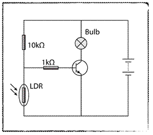
The diagram shows a circuit of an automatic switch. The bulb will light up when
CorrectIncorrect -
Question 8 of 12
8. Question
1 point(s)
The figure above shows the symbol of a logic gate. The logic gate is equivalent to a
CorrectIncorrect -
Question 9 of 12
9. Question
1 point(s)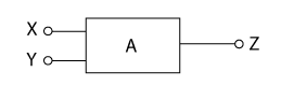
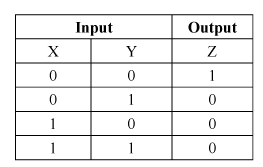
A is a logic gate with input X and Y. Z is the output of the logic gate. The truth table of the logic gate is shown in the table above. What type of logic gate is A?
CorrectIncorrect -
Question 10 of 12
10. Question
1 point(s)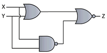
The diagram below shows a logic gate circuit. The input at P and Q are 1001 and 1100 respectively. What is the signal of the Z output?
CorrectIncorrect -
Question 11 of 12
11. Question
1 point(s)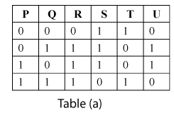
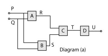
Diagram (a) above shows a combination of logic gates labelled A, B, C and D. Table (a) shows the truth table of the logic gate. Which of the following statements below are true?
CorrectIncorrect -
Question 12 of 12
12. Question
1 point(s)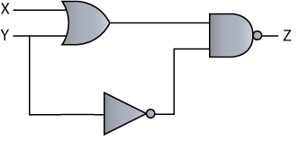
The circuit shown above is a series of logic gates in an electronic appliance. The truth table of the Z output is
CorrectIncorrect