Question 1:
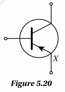
Figure 5.20 shows the symbol for an electronic device.
(a) What is the name of the electronic device?
(b) What is the function of terminal X on the electronic device?
Answer:
(a) pnp transistor
(b)
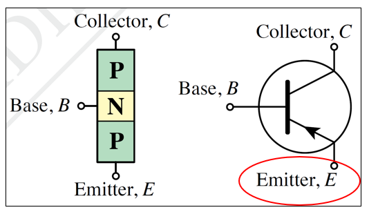
Supply charge carriers to the collector

Figure 5.20 shows the symbol for an electronic device.
(a) What is the name of the electronic device?
(b) What is the function of terminal X on the electronic device?
Answer:
(a) pnp transistor
(b)

Supply charge carriers to the collector
Question 2:
Figure 5.21 shows a transistor circuit which consists of two circuits, namely circuits A and B. When switch S is closed, bulb P is lighted dimly while bulb Q lights up brightly.
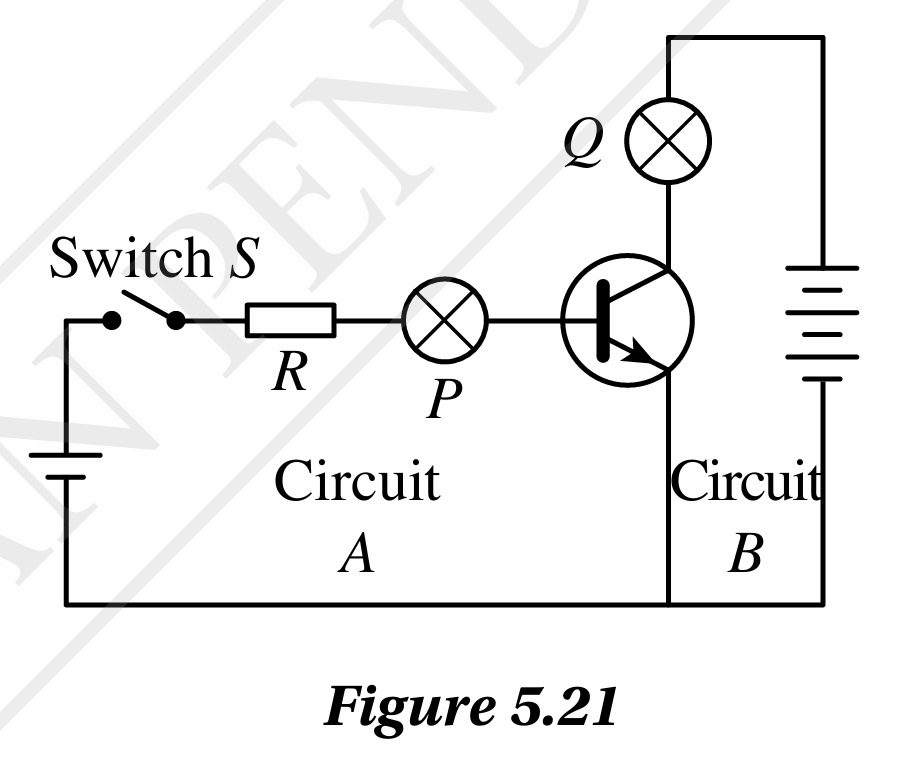
(a) Name circuit A and circuit B.
(b) Why does bulb P light up dimly when switch, S is closed?
(c) draw the modifications to the transistor circuit if the npn transistor is replaced with a pnp transistor.
Answer:
(a) A is the base circuit and B is the collector circuit.
(b) The current flowing through bulb P is very small.
(c)

Figure 5.21 shows a transistor circuit which consists of two circuits, namely circuits A and B. When switch S is closed, bulb P is lighted dimly while bulb Q lights up brightly.

(a) Name circuit A and circuit B.
(b) Why does bulb P light up dimly when switch, S is closed?
(c) draw the modifications to the transistor circuit if the npn transistor is replaced with a pnp transistor.
Answer:
(a) A is the base circuit and B is the collector circuit.
(b) The current flowing through bulb P is very small.
(c)

Question 3:
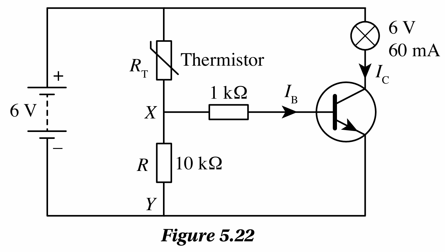
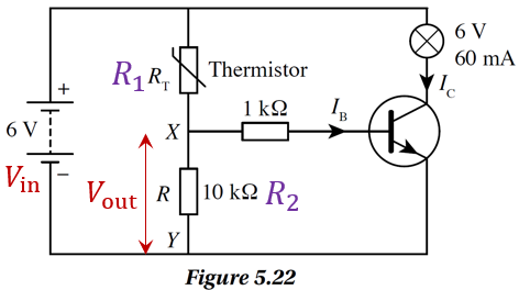
Figure 5.22 shows a temperature-controlled alarm circuit. Resistor, R has a resistance of 10 kW. The potential difference across XY must be at least 5.5 V to turn on the 6 V, 60 mA bulb. What is the resistance of the thermistor when the bulb lights up?
Answer:
$$ \text { Potential difference, } V_0=6 \mathrm{~V} $$
$$ \text { Resistance, } R=10 \mathrm{k} \Omega $$
$$ \text { Potential difference across } X Y, V_{\mathrm{XY}}=5.5 \mathrm{~V} $$
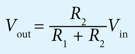
$$ \begin{aligned} V_{\mathrm{XY}} & =\frac{10}{R_{\mathrm{T}}+10} \times 6 \\ 5.5 & =\frac{10}{R_{\mathrm{T}}+10} \times 6 \\ R_{\mathrm{T}}+10 & =\frac{60}{5.5} \end{aligned} $$
$$ \text { Thermistor resistance, } \begin{aligned} R_{\mathrm{T}} & =\frac{60}{5.5}-10 \\ & =10.9-10 \\ & =0.9 \mathrm{k} \Omega \end{aligned} $$

Figure 5.22 shows a temperature-controlled alarm circuit. Resistor, R has a resistance of 10 kW. The potential difference across XY must be at least 5.5 V to turn on the 6 V, 60 mA bulb. What is the resistance of the thermistor when the bulb lights up?
Answer:


$$ \text { Potential difference, } V_0=6 \mathrm{~V} $$
$$ \text { Resistance, } R=10 \mathrm{k} \Omega $$
$$ \text { Potential difference across } X Y, V_{\mathrm{XY}}=5.5 \mathrm{~V} $$
$$ \begin{aligned} V_{\mathrm{XY}} & =\frac{10}{R_{\mathrm{T}}+10} \times 6 \\ 5.5 & =\frac{10}{R_{\mathrm{T}}+10} \times 6 \\ R_{\mathrm{T}}+10 & =\frac{60}{5.5} \end{aligned} $$
$$ \text { Thermistor resistance, } \begin{aligned} R_{\mathrm{T}} & =\frac{60}{5.5}-10 \\ & =10.9-10 \\ & =0.9 \mathrm{k} \Omega \end{aligned} $$
