
Question 7:
A wooden block with volume 3.24 × 10⁻³ m3 is released in a tank of water. By doing the relevant calculations, sketch the state of buoyancy of the wooden block in the tank.
[Density of wood, ρ = 920 kg m–3, density of water, ρ = 1 000 kg m–3 and gravitational acceleration, g = 9.81 m s–2]
Answer:
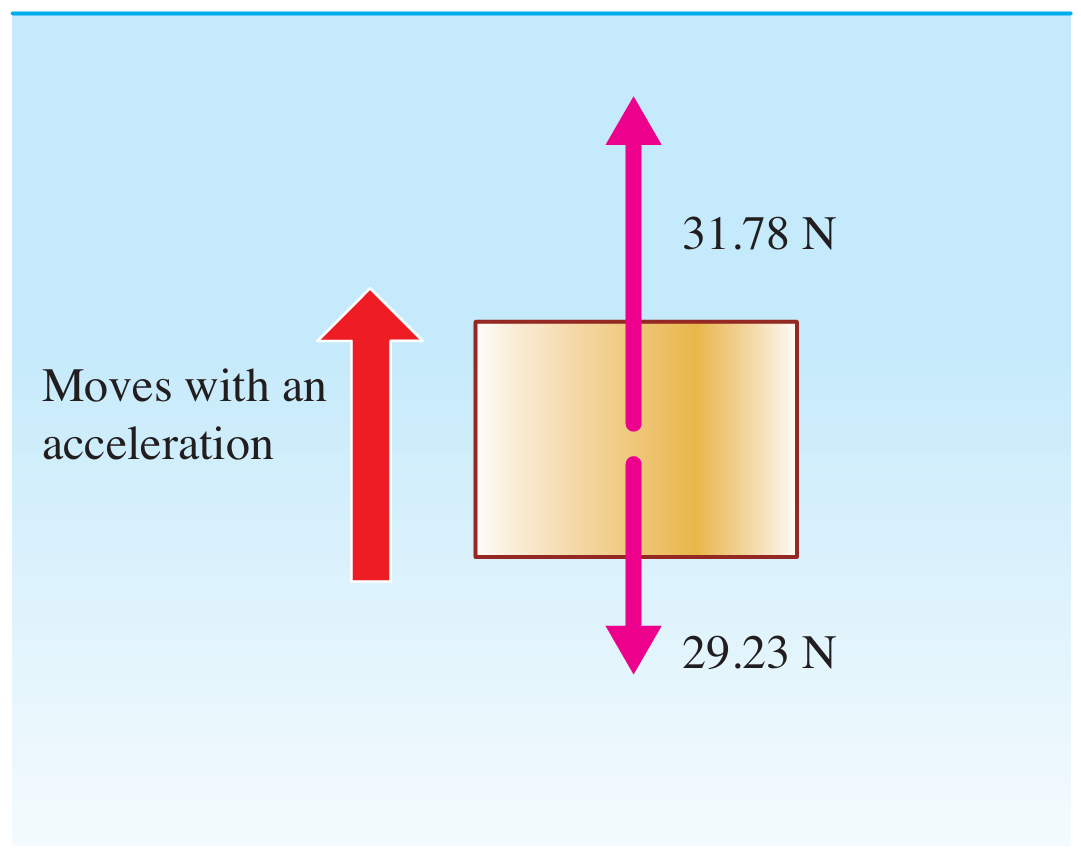
$$ \begin{aligned} & \text { Mass of wooden block }=3.24 \times 10^{-3} \times 920=2.98 \mathrm{~kg} \\ & \text { Weight of wooden block }=2.98 \times 9.81=29.23 \mathrm{~N} \\ & \begin{aligned} \text { Buoyant force } & =3.24 \times 10^{-3} \times 1000 \times 9.81 \\ & =31.78 \mathrm{~N} \end{aligned} \end{aligned} $$
$$ \text { Buoyant force }>\text { weight of block } $$
There is a resultant force upwards
The block moves up with an acceleration
A wooden block with volume 3.24 × 10⁻³ m3 is released in a tank of water. By doing the relevant calculations, sketch the state of buoyancy of the wooden block in the tank.
[Density of wood, ρ = 920 kg m–3, density of water, ρ = 1 000 kg m–3 and gravitational acceleration, g = 9.81 m s–2]
Answer:
$$ \begin{aligned} & \text { Mass of wooden block }=3.24 \times 10^{-3} \times 920=2.98 \mathrm{~kg} \\ & \text { Weight of wooden block }=2.98 \times 9.81=29.23 \mathrm{~N} \\ & \begin{aligned} \text { Buoyant force } & =3.24 \times 10^{-3} \times 1000 \times 9.81 \\ & =31.78 \mathrm{~N} \end{aligned} \end{aligned} $$
$$ \text { Buoyant force }>\text { weight of block } $$
There is a resultant force upwards
The block moves up with an acceleration
Question 8:
Figure 3 shows two designs of a hydraulic jack, X and Y which were suggested by a technician.
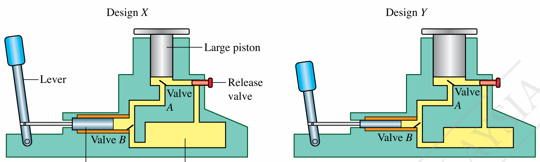
(a) By referring to design X, describe the operation of the hydraulic jack.
(b) Study design X and design Y. Compare the advantages and disadvantages of design X and design Y.
(c) Based on your answer in 8(b), suggest a design of hydraulic jack that can produce a larger output force and lift a load to a greater height.
Answer:
(a)
The handle of the lever is pulled to the right.
An input force acts on the small piston.
The input force produces a pressure on the hydraulic oil.
Valve A opens, valve B closes.
Pressure is transmitted to the large piston.
A larger output force moves the large piston upwards.
The handle of the lever is pulled to the left.
Valve A closes, valve B opens.
The large piston stays at the same position. Hydraulic oil flows from the reservoir into the small cylinder.
This process is repeated so that the large piston is moved a little at a time.
(b)
• Lever: Design X is better than design Y.
A longer lever enables a larger input force to be exerted on the small piston.
• Cross-sectional area of small piston and large piston: Design Y is better than design X.
$$ \text { Output force, } F_2=\frac{A_2}{A_1} \times F_1 $$
$$ \begin{aligned} & A_2=\text { cross-sectional area of large piston } \\ & A_1=\text { cross-sectional area of small piston } \\ & F_1=\text { input force } \end{aligned} $$
$$ \text { Design } Y \text { has larger } A_2 \text { and a smaller } A_1 $$
$$ \text { to give a larger multiplying factor } \frac{A_2}{A_1} $$
• Volume of oil reservoir: Design X is better than design Y
Design X has a larger volume of oil. More oil can be moved from the small cylinder to the large cylinder.
The load on the large piston can be lifted to a greater height.
(c)
Suggested design:
– Longer lever
– Smaller cross-sectional area for the small piston
– Larger cross-sectional area for the large piston
– Oil reservoir with a larger volume
Figure 3 shows two designs of a hydraulic jack, X and Y which were suggested by a technician.
(a) By referring to design X, describe the operation of the hydraulic jack.
(b) Study design X and design Y. Compare the advantages and disadvantages of design X and design Y.
(c) Based on your answer in 8(b), suggest a design of hydraulic jack that can produce a larger output force and lift a load to a greater height.
Answer:
(a)
The handle of the lever is pulled to the right.
An input force acts on the small piston.
The input force produces a pressure on the hydraulic oil.
Valve A opens, valve B closes.
Pressure is transmitted to the large piston.
A larger output force moves the large piston upwards.
The handle of the lever is pulled to the left.
Valve A closes, valve B opens.
The large piston stays at the same position. Hydraulic oil flows from the reservoir into the small cylinder.
This process is repeated so that the large piston is moved a little at a time.
(b)
• Lever: Design X is better than design Y.
A longer lever enables a larger input force to be exerted on the small piston.
• Cross-sectional area of small piston and large piston: Design Y is better than design X.
$$ \text { Output force, } F_2=\frac{A_2}{A_1} \times F_1 $$
$$ \begin{aligned} & A_2=\text { cross-sectional area of large piston } \\ & A_1=\text { cross-sectional area of small piston } \\ & F_1=\text { input force } \end{aligned} $$
$$ \text { Design } Y \text { has larger } A_2 \text { and a smaller } A_1 $$
$$ \text { to give a larger multiplying factor } \frac{A_2}{A_1} $$
• Volume of oil reservoir: Design X is better than design Y
Design X has a larger volume of oil. More oil can be moved from the small cylinder to the large cylinder.
The load on the large piston can be lifted to a greater height.
(c)
Suggested design:
– Longer lever
– Smaller cross-sectional area for the small piston
– Larger cross-sectional area for the large piston
– Oil reservoir with a larger volume